

Ibis trackers are SlimeVR Compatible full body tracking devices. They are a “Smol” slime, which means they use NRF instead of wifi to connect to your PC. NRF is like bluetooth, but with less lag. To learn more, please visit the SlimeVR Documentation on Smol Slimes.
Ibis Trackers are completely open source, which means you can build your own if you have the time. They are identical to the product we sell. This guide will show you the process we take for each tracker.
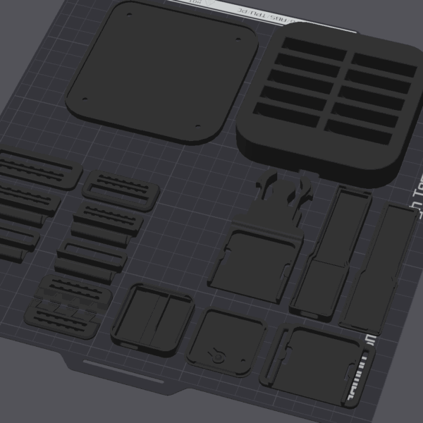
Parts Required
To make your trackers, you’ll need access to a 3D printer. You can also buy the 3D printed parts from us. You’ll also need:
- a Stanley knife (or something very sharp)
- wire cutters
- wire strippers
- kapton tape
- a fine tip soldering iron specifically for electronics (best if it has temperature control)
- Solder with Flux
- other tools you think may make the process easier.
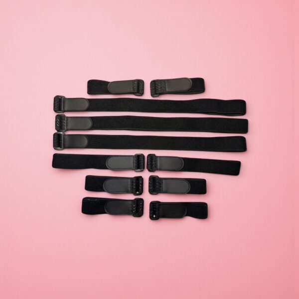
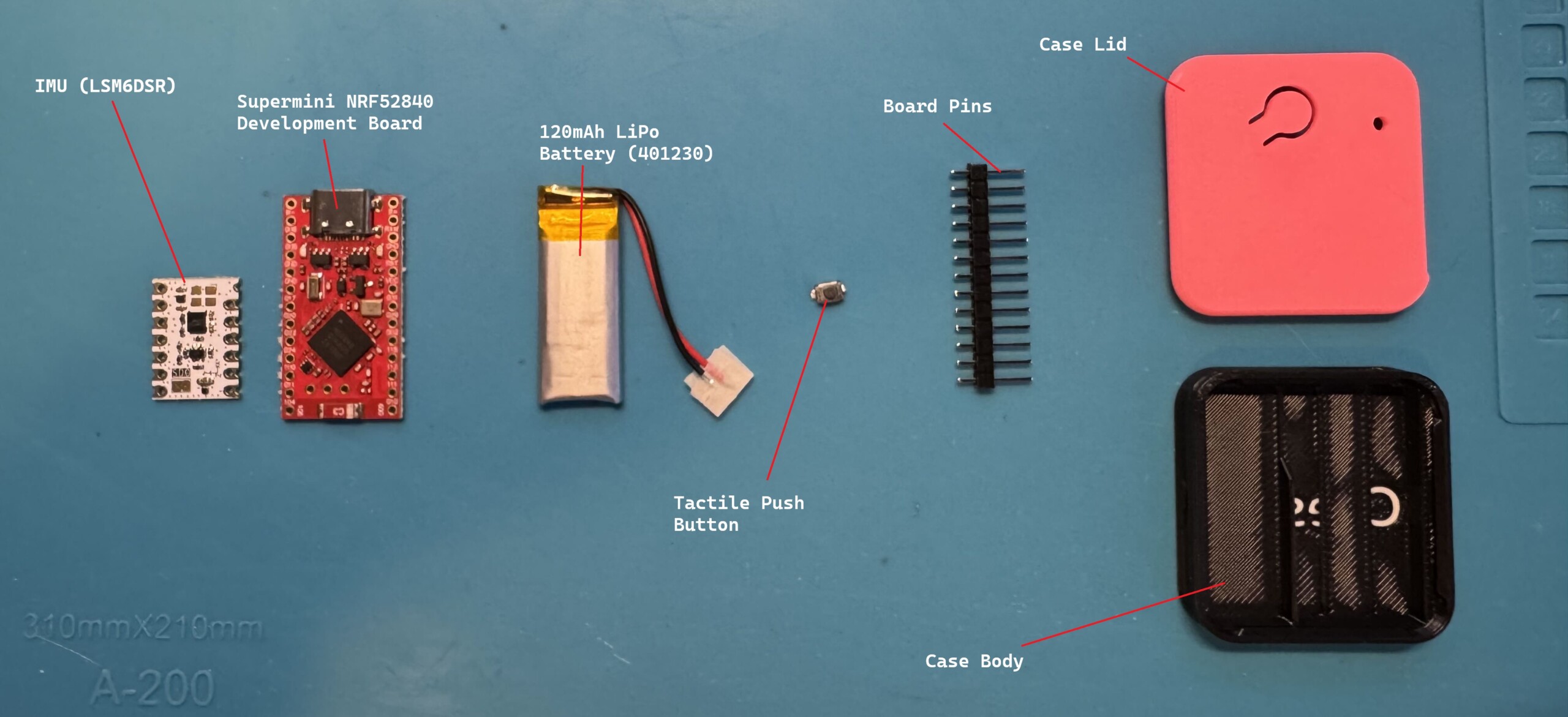
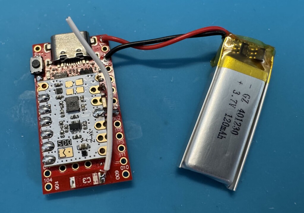
Tracker Components
Each tracker is made up of a few simple components:
- IMU Module (ICM-45686 or LSM6DSR)
- Supermini NRF52840 board OR Seed Studio equivalent
- 120mAh LiPo battery
- Small, tactile push button
- Board pins (should have come with your Supermini)
- Wire for the antenna mod

Component Preparation
To ensure each component fits correctly and works, there are a few steps we need to take before we assemble each tracker.
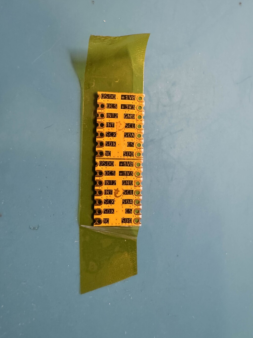
IMU
The IMU will most likely come in rows of 5, and will have some little defects we want to shave off. Before then, if you still have them connected, you’ll need to add some kapton tape to the back of them. This prevents solder from seeping through onto the supermini board later.
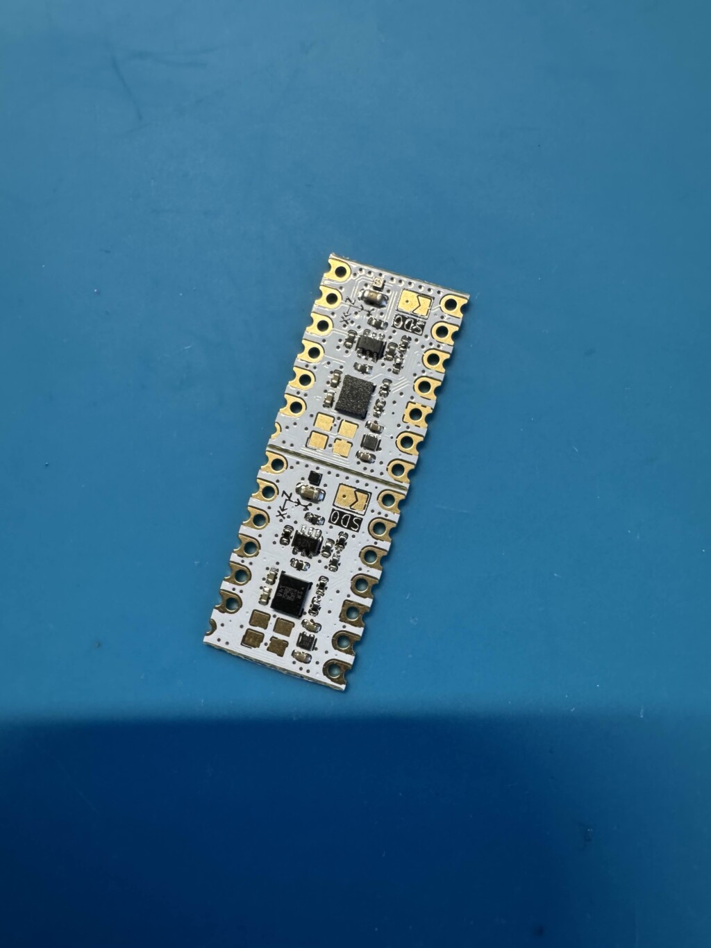
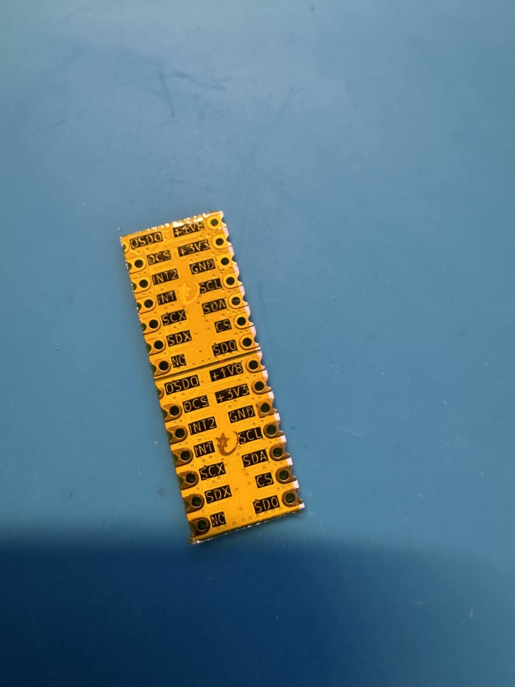
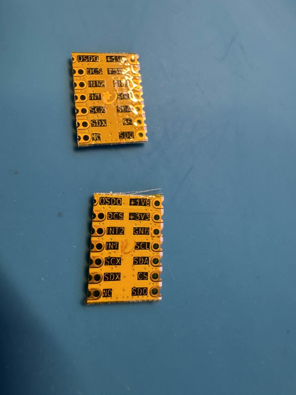
Once you’ve separated and taped your IMU’s, you’ll want to shave off the excess from the top and bottom. This isn’t a required step, but helps clean them up a bit.
It doesn’t have to be perfect.
Pre-Soldering The IMU
This step is as far as I can tell, unique to our process. I designed a “Soldering Cube” to help make this process less likely to destroy part of the SuperMini.
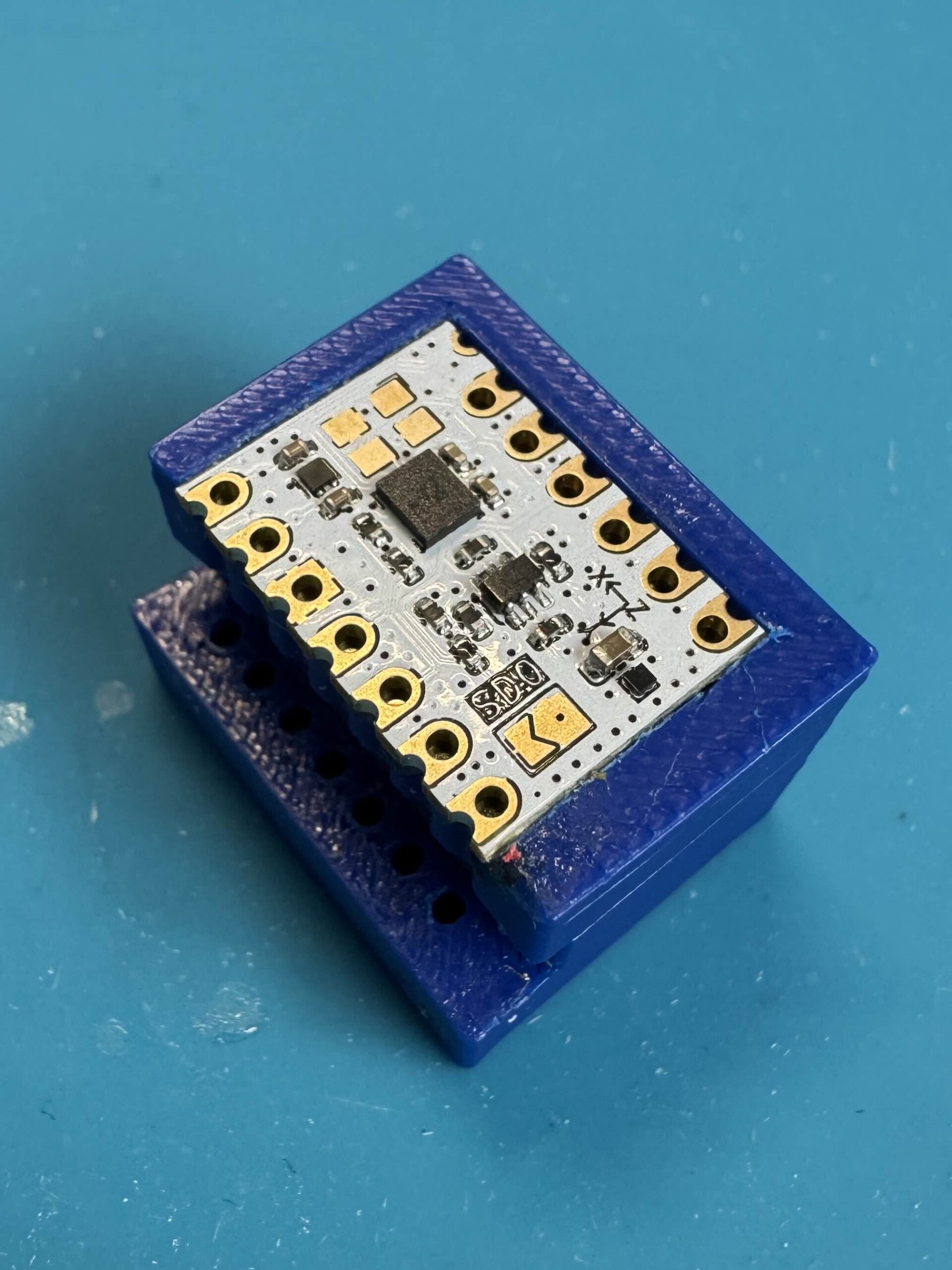
You can get a Soldering Cube here.
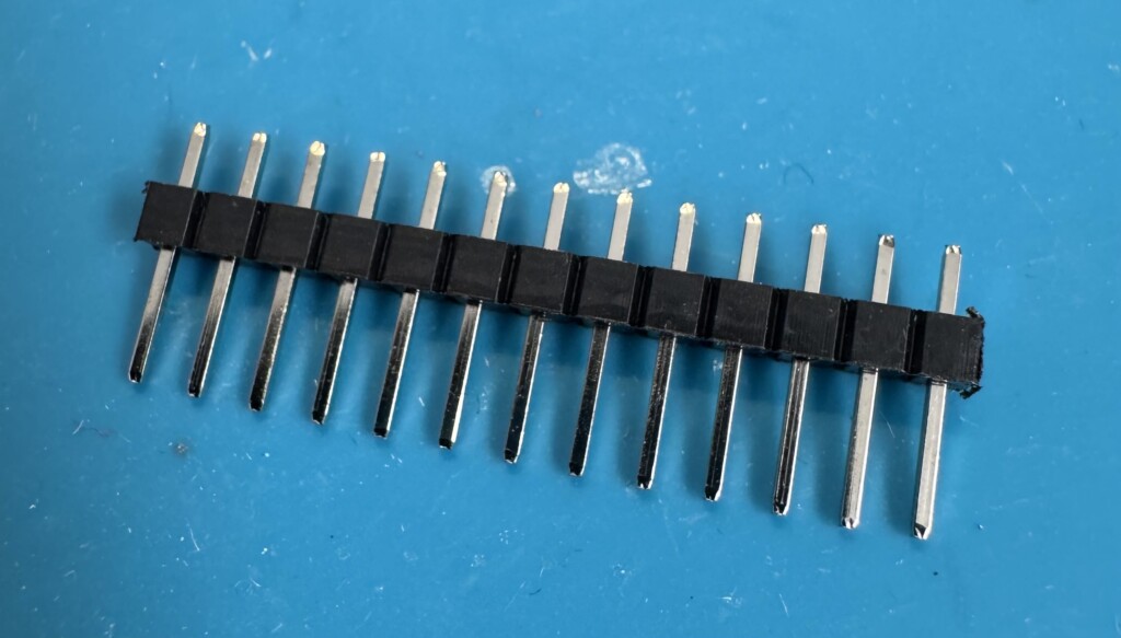
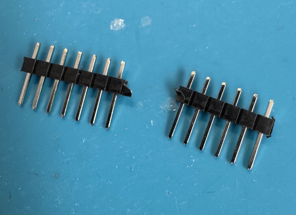
Take your pins, and split them in half. You’ll need a row of six:
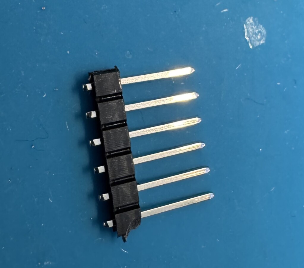
Push the plastic on the 6 pins down towards the bottom. I use a breadboard to push the pins down easily. I also do this on my soldering mat, so they don’t go ALL the way to the bottom. about 1mm at the end is right.
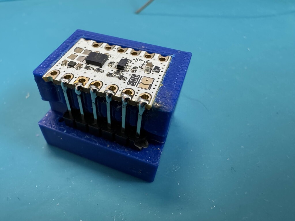
Place the pins in the soldering cube with the IMU
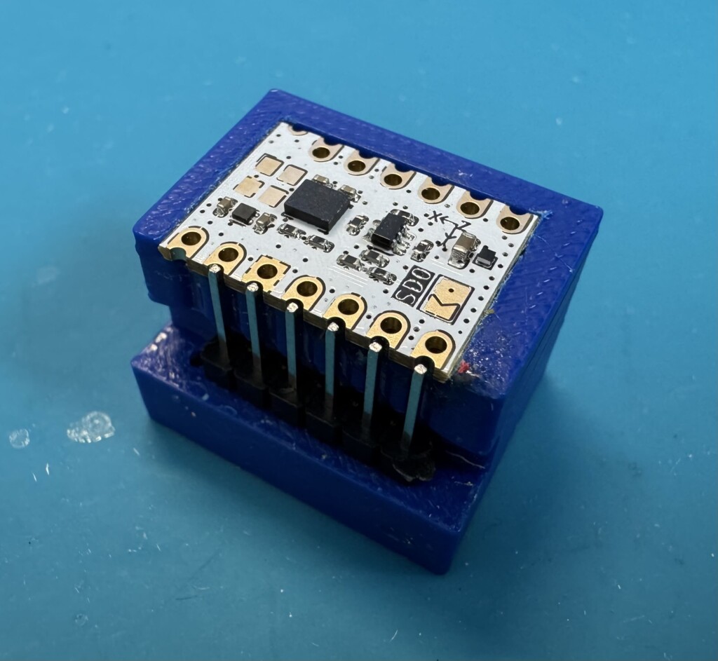
Tile the cube on the side so we can more easily solder the pins.
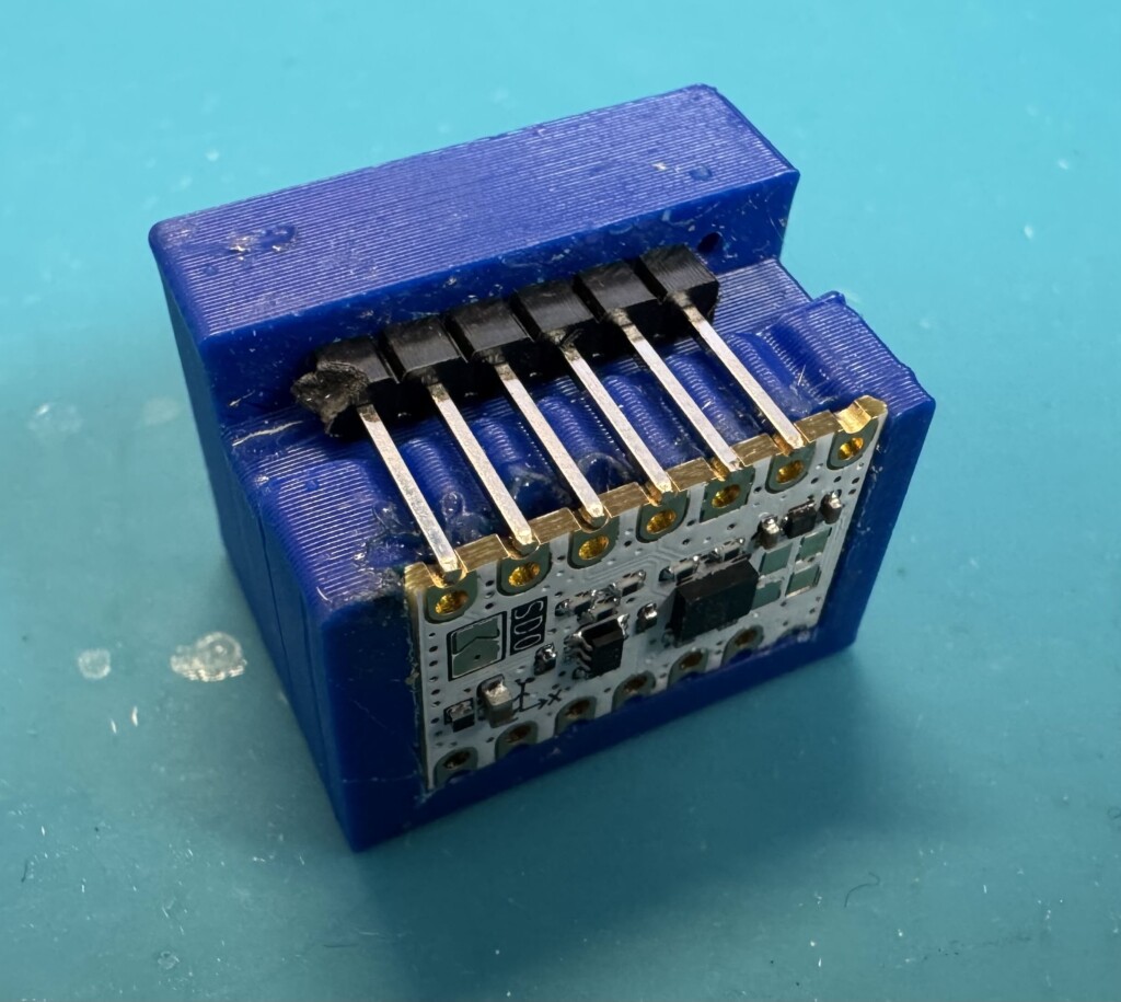
I prefer to solder the left, then the right most pins, then the inner ones. Just a little bit of solder first, then if you want, you can strengthen the connections with a bit more solder.
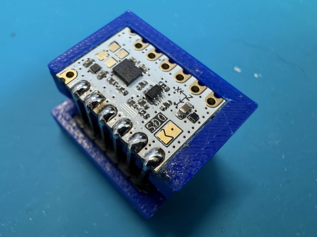
Once you’re happy with your joints, I recommend cleaning it with a bit of Isopropyl alchohol or PCB cleaner to remove any flux from the soldering process.
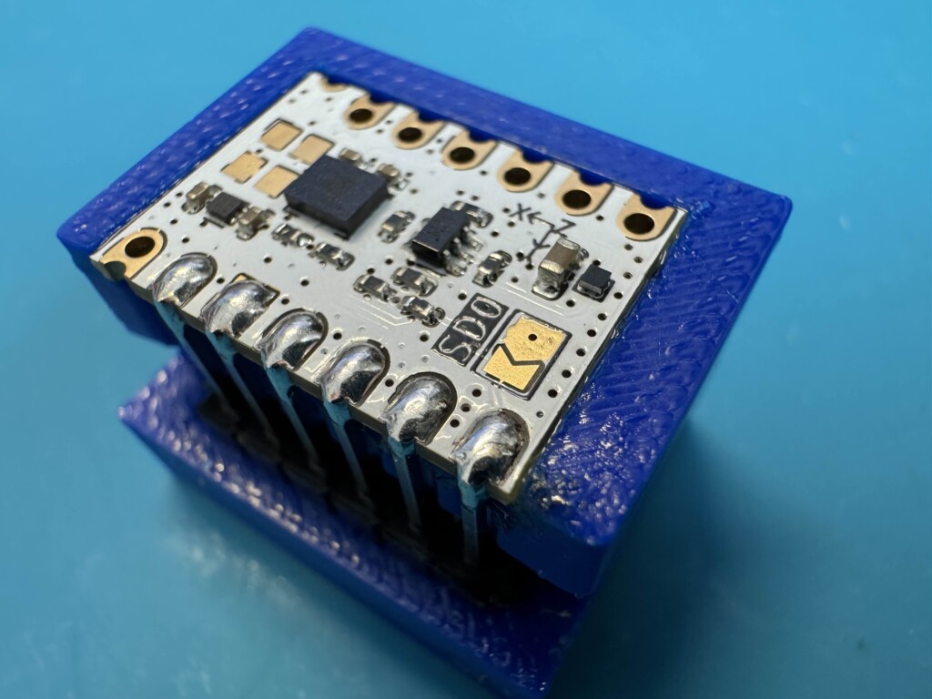
Remove the IMU from the soldering cube, and snip the pins as close to the plastic as possible. You can attempt the just slide the plastic off, but this risks pulling the pins off of the IMU.
Now onto the SuperMini!
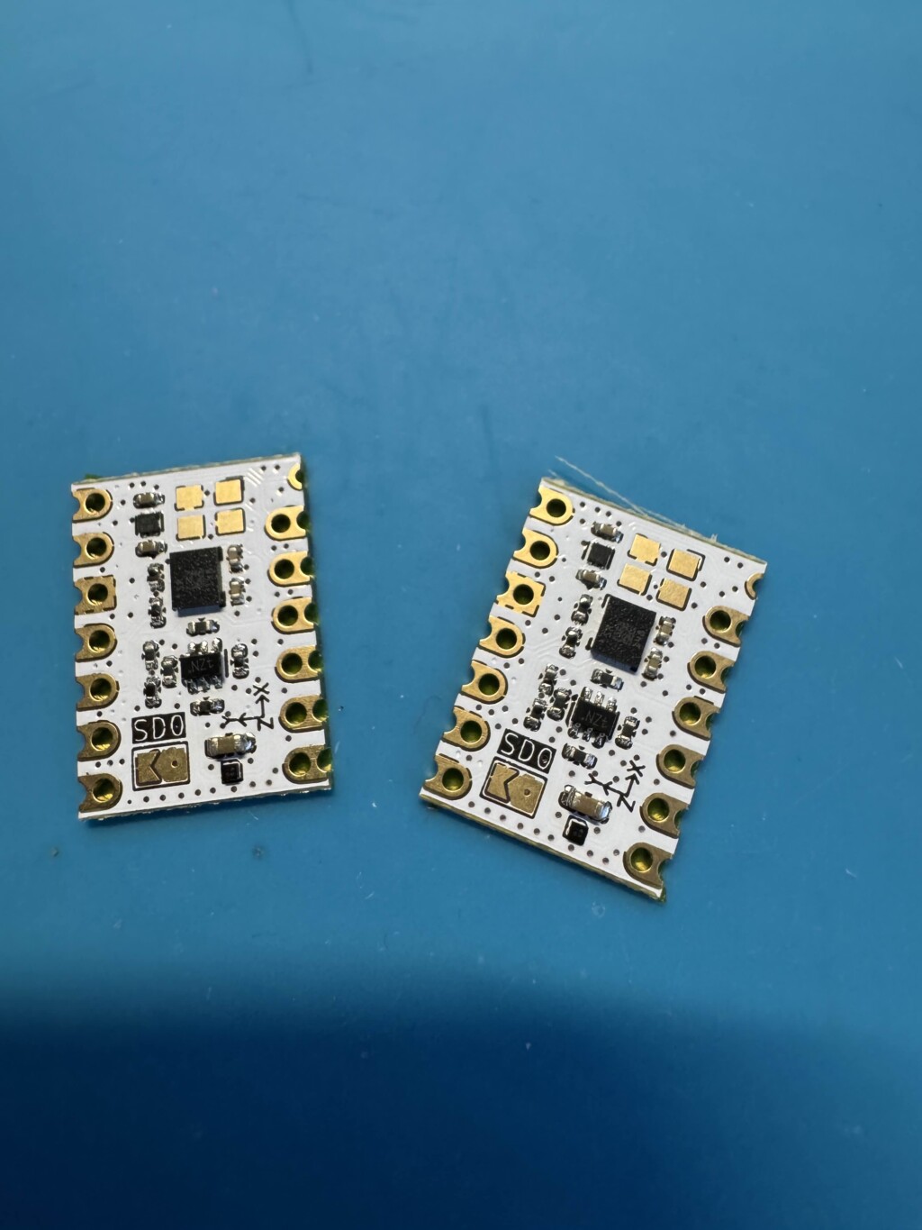
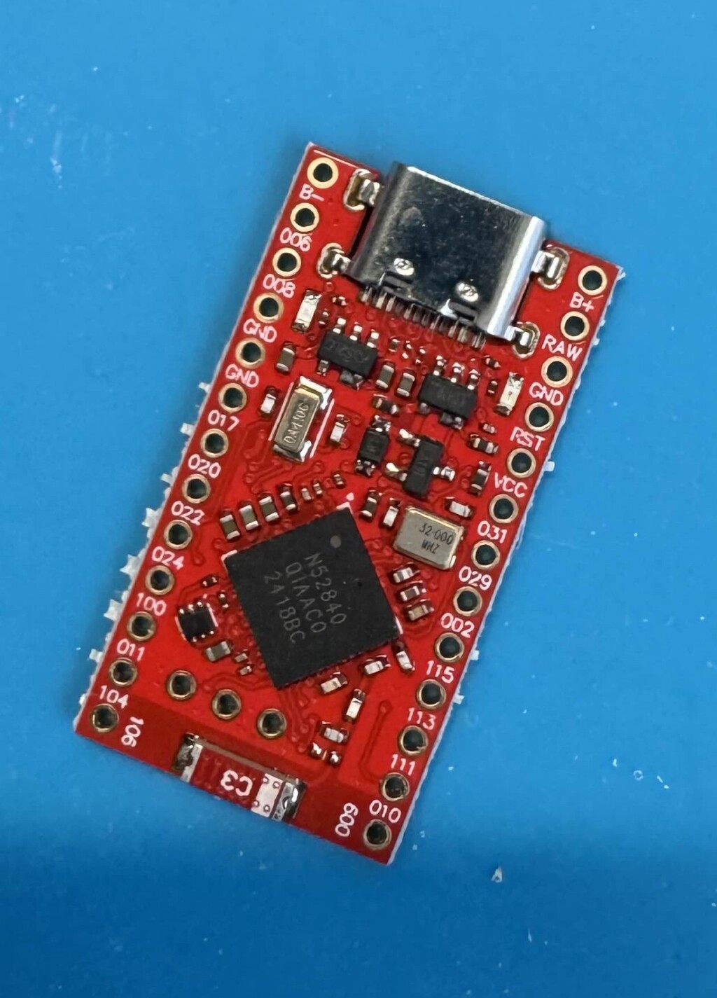
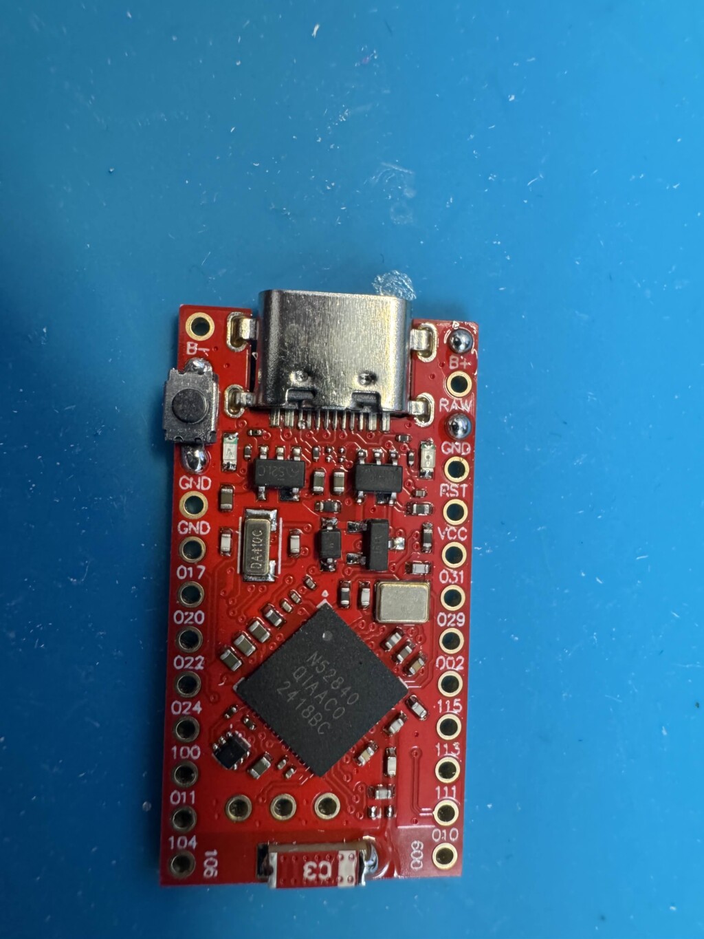
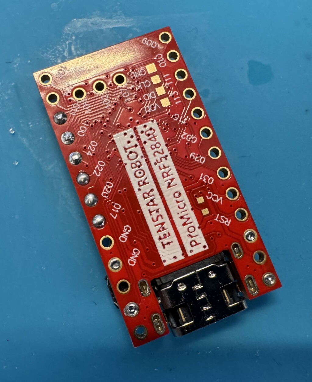
Supermini NRF52840
For the Supermini development board, there are 3 steps to prepare this one. It’s also your main tracker board, so mostly all steps will focus on this device.
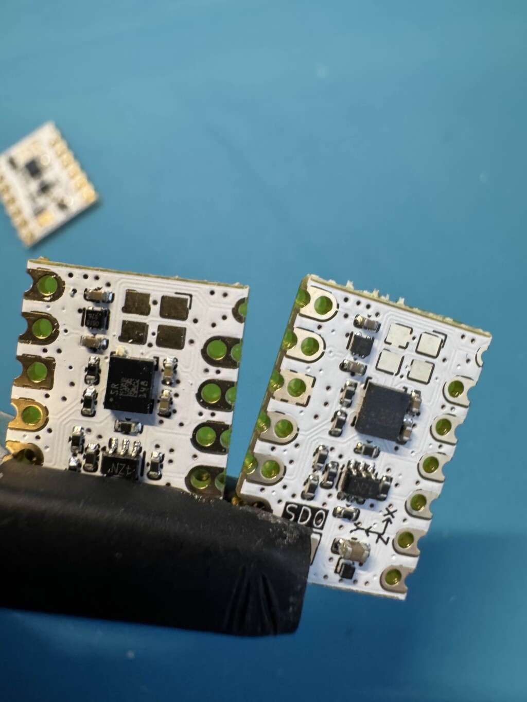
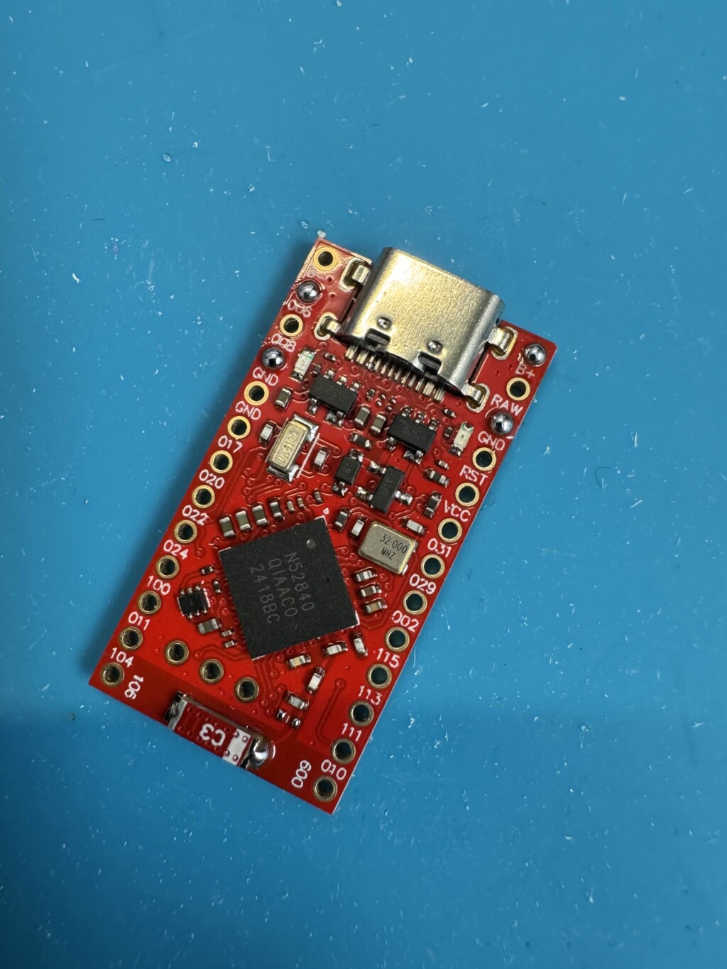
Preparing the board
As with the IMU, you’ll want to shave off the excess from the sides of the unit. This is a requirement, otherwise it will not fit inside the case.
Firmware Flashing
Before we start soldering, it’s best to ensure that the SuperMini actually works. Connect it via USB to your PC, and open the Serial Terminal in NRF Connect for Desktop App. The first sign of a good board is that it should be blinking like the following:
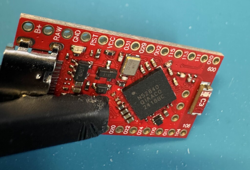
Next, we need to short the RST button to the GND pin. Alternatively, you can be the ground, and just use something metal to short the RST pin like this:
Once you’ve shorted the pin by tapping it 2 times (sometimes it takes 2-5 times) the red light will fade/flash solid. Then, you can copy the Bootloader .uf2 file to update the device BEFORE we flash it with the tracker firmware.
Download the Bootloader firmware here.
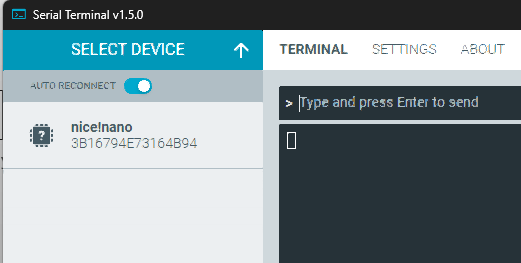
To copy the firmware, simply copy/paste the bootloader file above to the “NiceNano” drive that appears in your computer. It should look like a USB Drive.

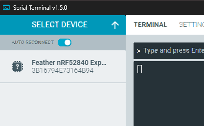
Your SuperMini will reset, and the drive will disappear. If you see it in the Terminal, it most likely worked. It may appear like a “Feather” device in your Serial Terminal.
Next, we need to flash the SlimeVR Tracker Firmware.
Download the latest SlimeVR Tracker Firmware here.
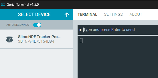
Short the RST pin again and copy the above file. Once done, the tracker should appear in the terminal like this:
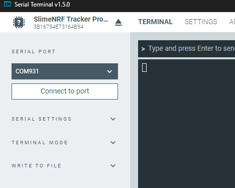
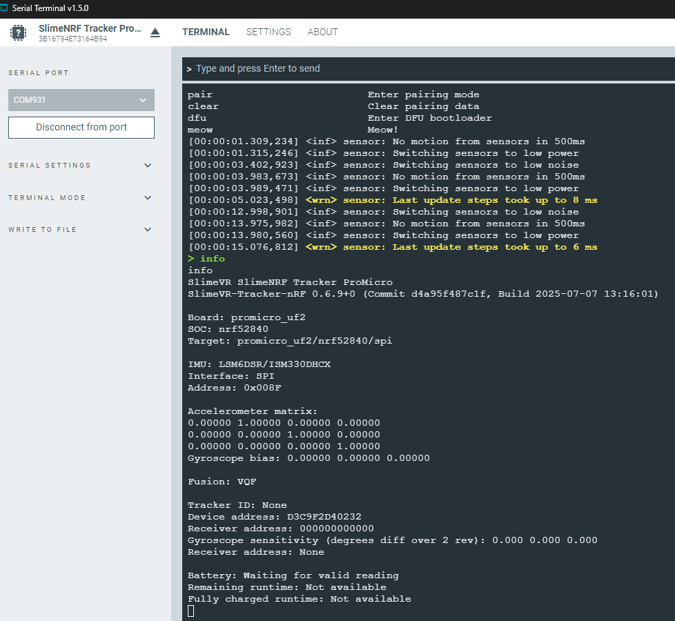
You can now connect to the tracker, and check everything so far is working:
Looks like we’re working!
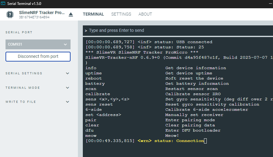
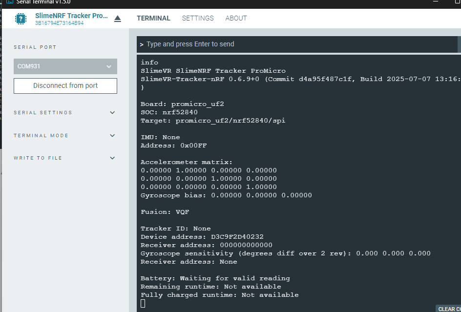
in the text input above the console, type “info”:
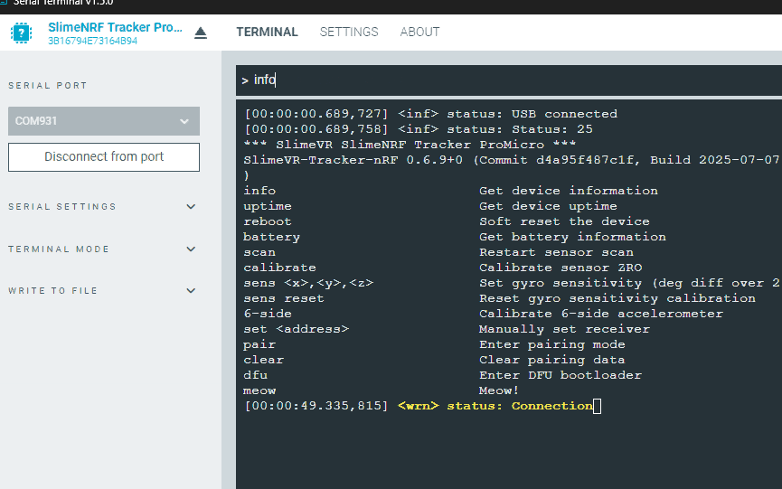
Great! That’s enough for us to continue to the next stage.
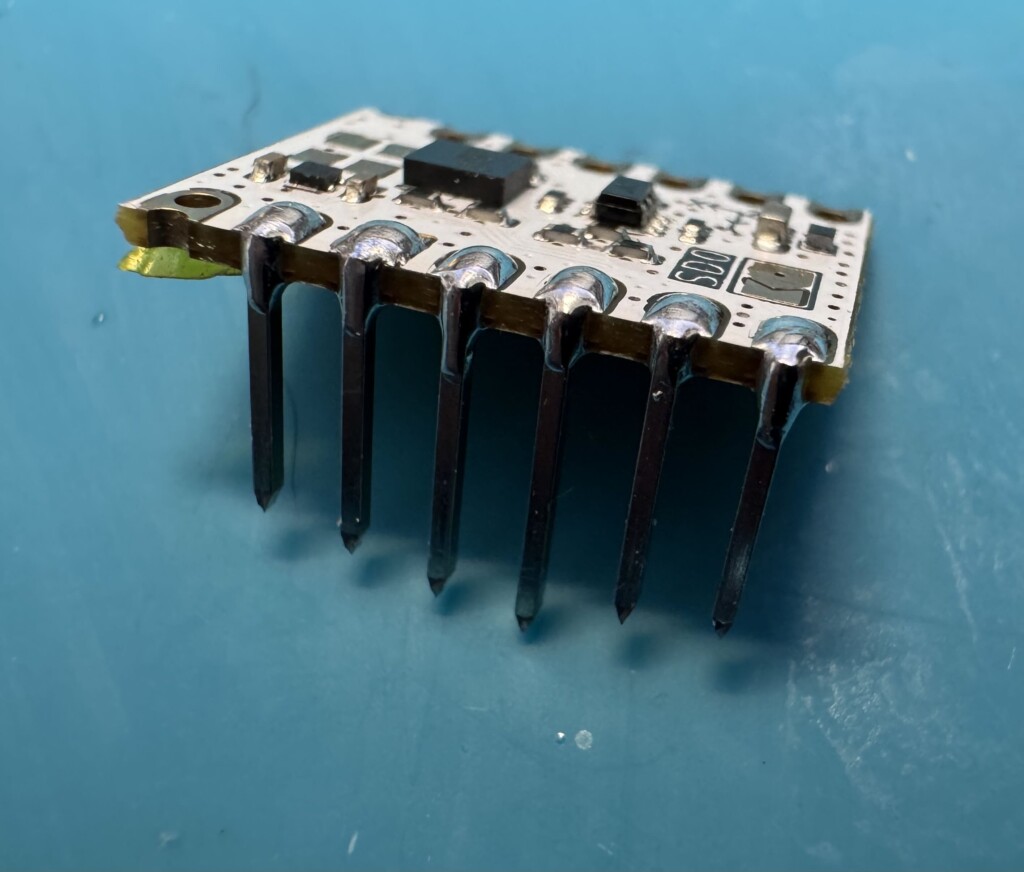
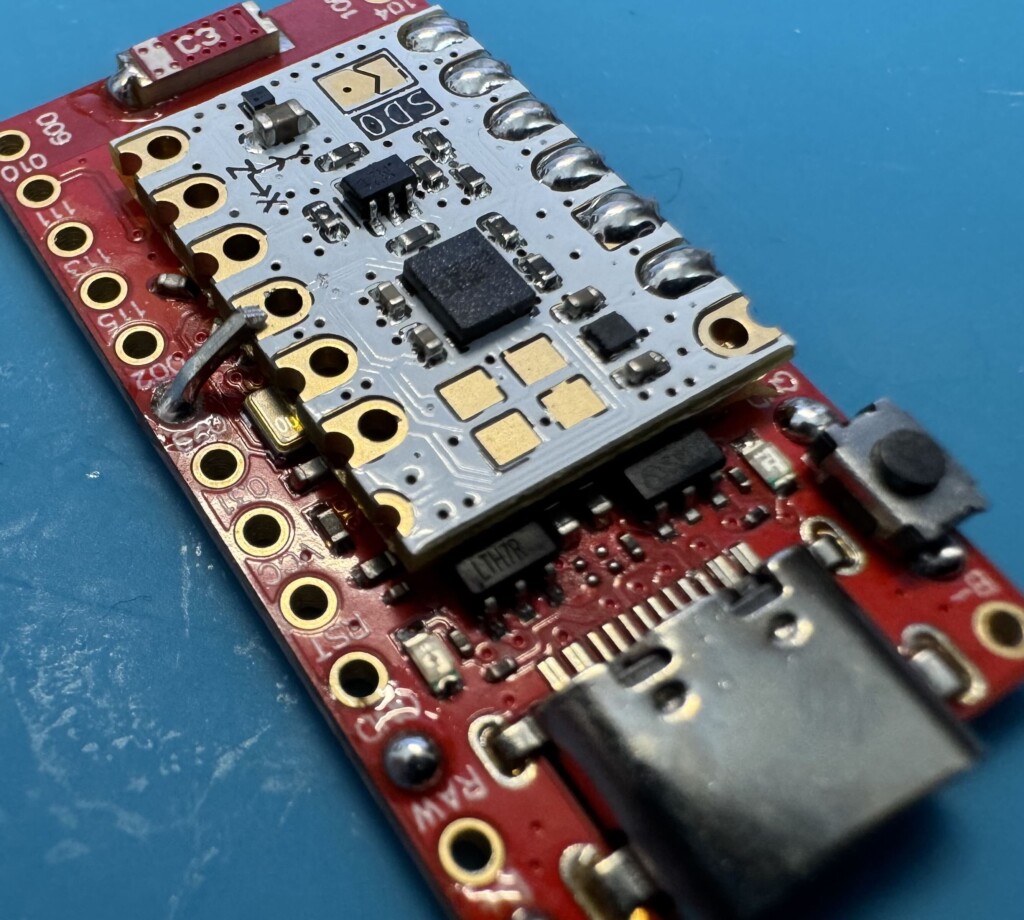
Pre Soldering the board
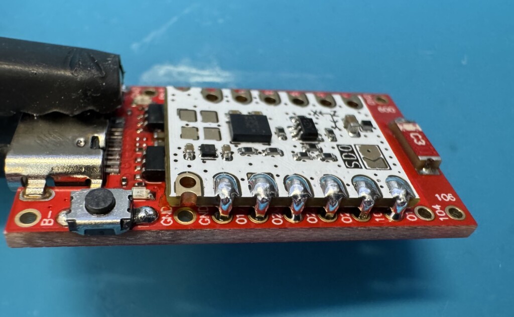
There’s a few points I prefer to pre solder to make life easier for us later. Fill the following pins with solder. We’re adding solder to the battery connectors, button contacts, and the antenna for the antenna mod (right side only!)
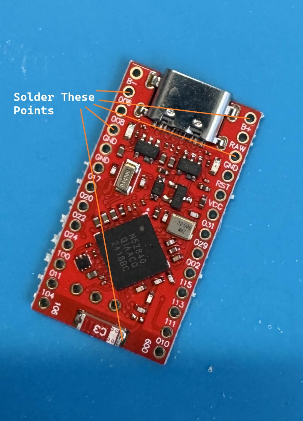
Lastly, we want to pre solder the button.
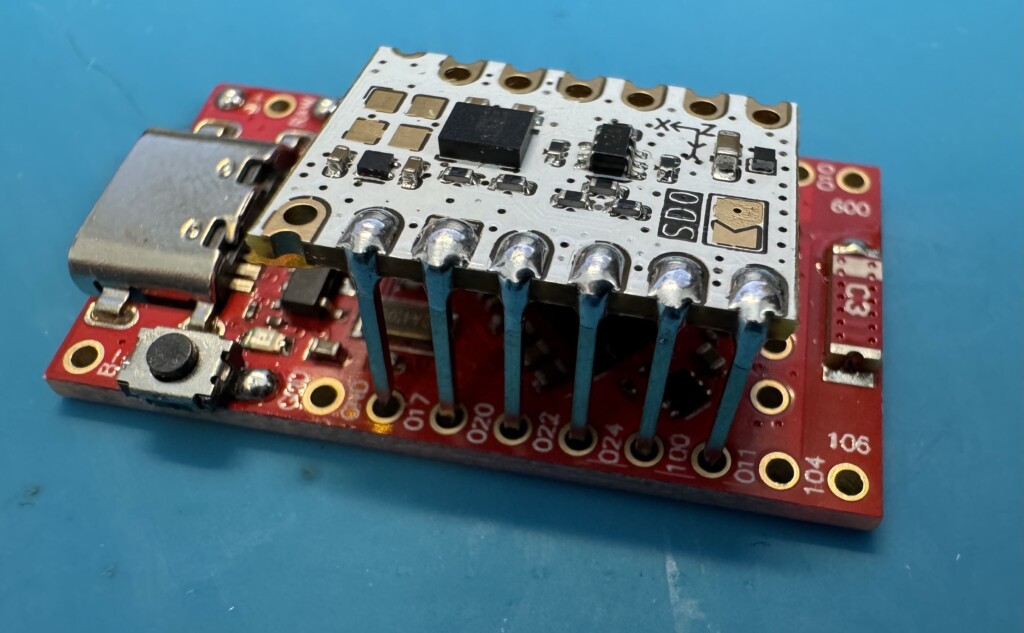
Assembly
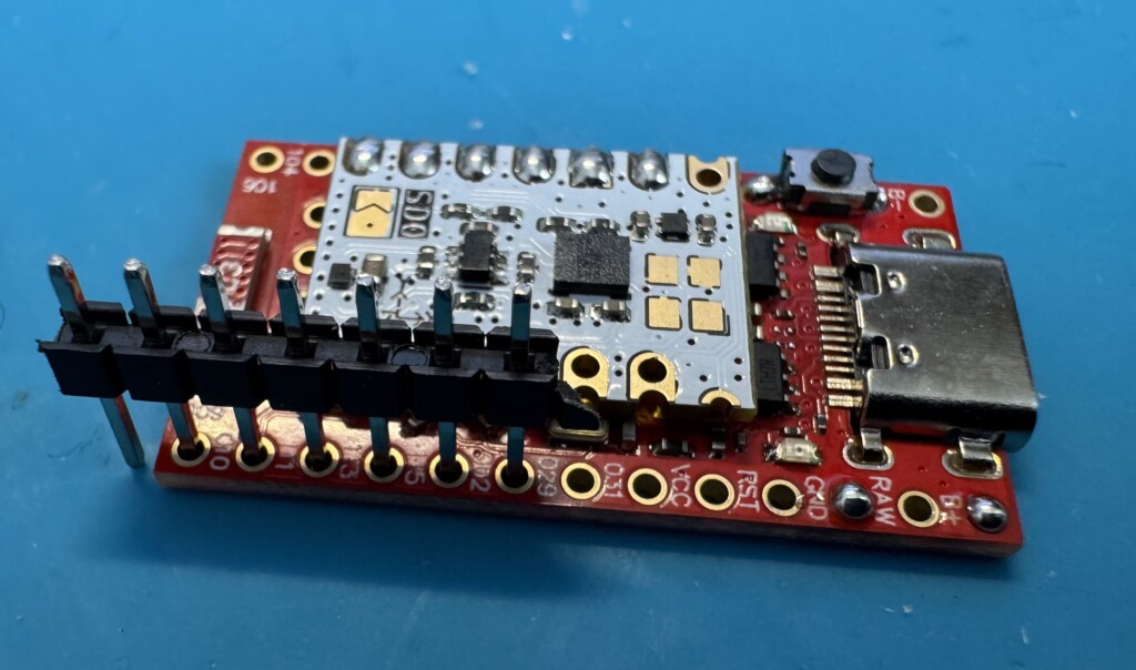
To assemble the IMU to the SuperMini, we need to connect the 6 pins from the left side of the IMU to the 6 pins on the left side of the SuperMini starting from the THIRD PIN, 011.
Flip the supermini upside down with the IMU in the correct pins, and snip off the excess pin length:
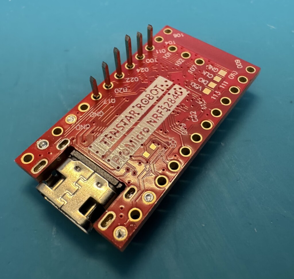
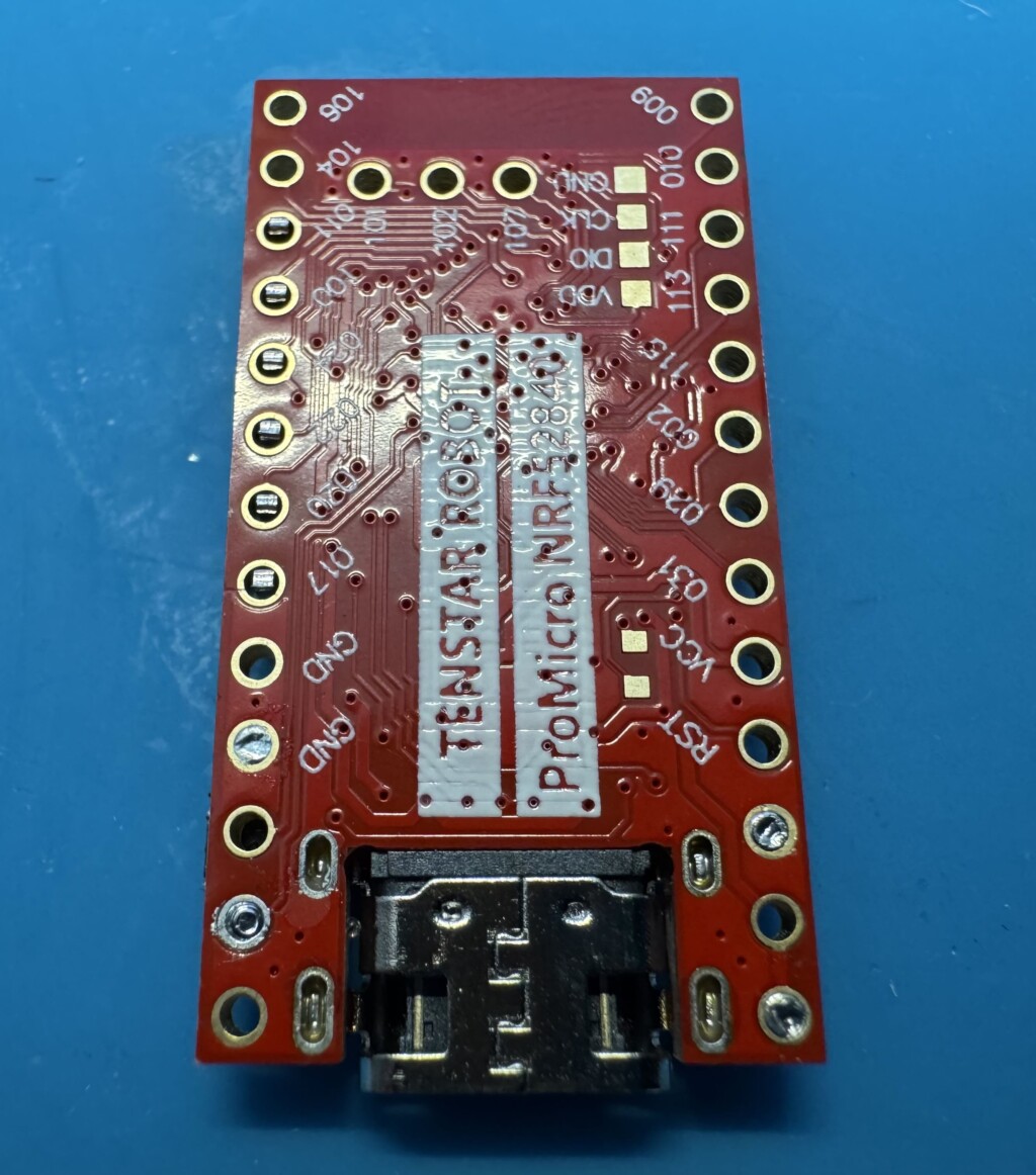
Solder the pins from the back, and clean off any excess Flux from your solder job.
Usually, you should solder the pins so they are creating a good contact. This one is okay because the pins are connected correctly from the back. Notice on most of these, they don’t appear to have a good soldered connection on the top. I find this to be okay, and even optimal, because too much solder can short the connections with one another.
Check the connection
Before we do the final assembly steps, you’ll want to connect the tracker to your PC and check to see if the IMU is detected. If it’s detected, you should see info logs about motion and status switching. Type “info” into the text box, and you should see something like this:
If your terminal is being spammed with yellow warnings, type “Reboot” and this should hopefully clear it. If no IMU is detected, you may need to go backk and check your soldering connections and try again.
In our case, everything is working as expected, so we can solder the last pin, “002”, on the right hand side. Note that the pins labels are UNDER the pins, not above. so you want to solder a pin in the hole between “002” and “029”.
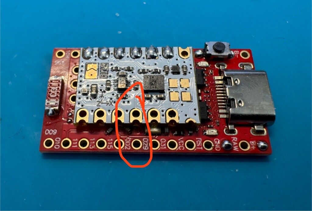
Using the remaining pins, place them in the holes. Solder pin “002”.
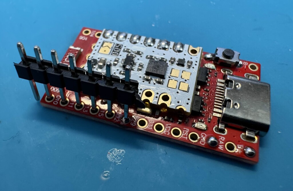
You should be able to then pull out the rest of the pins from the plastic, leaving just the one remaining.
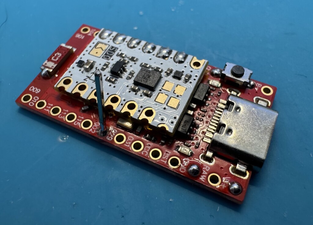
NOTE: If you are using ICM-45686 modules, you will ALSO need to solder the lower most pin on the IMU to pin 111 on the SuperMini. Leaving you with two soldered pins on the right side.
Fold the pin down so it’s touching the IMU, then snip the top.
Solder the connection, and be sure to clean off any flux.
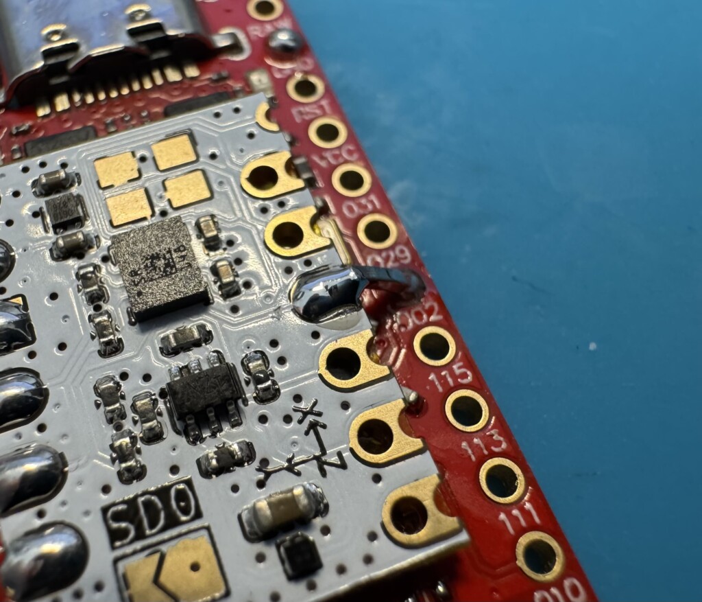
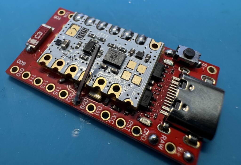
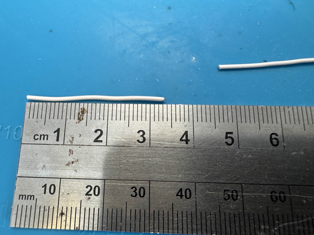
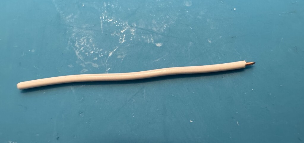
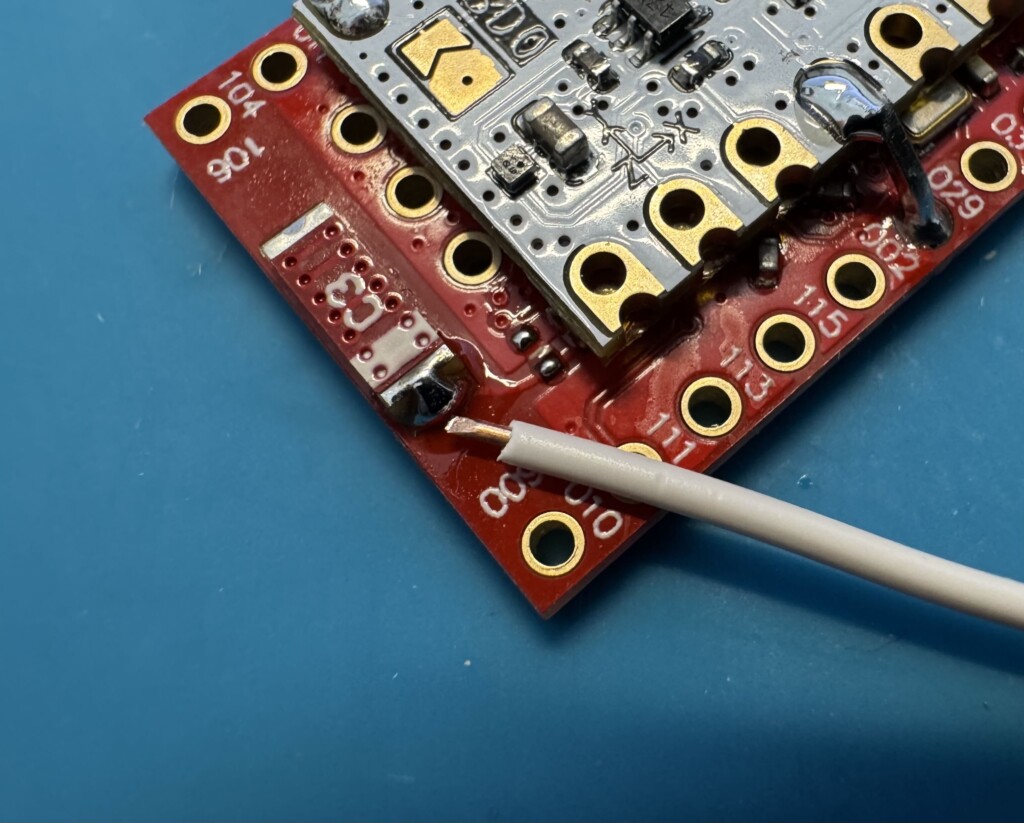
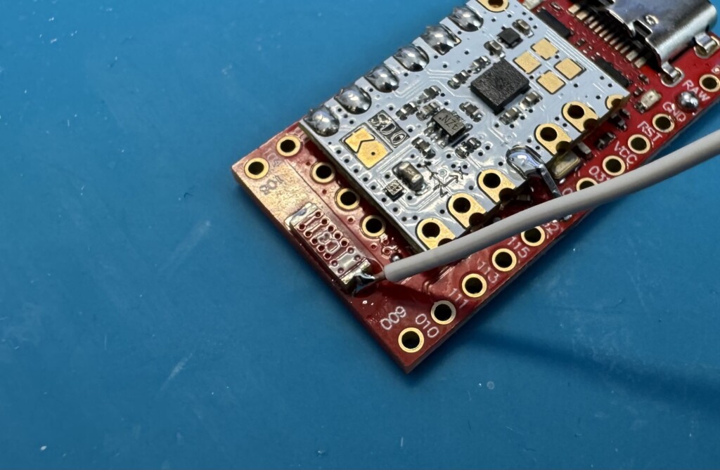
Connecting the Wire Mod
SuperMinis have horrendous signal strength as they are. To get the most out of them, the best option is to cut a 31mm wire (3.1cm) and connect it to the RIGHT side of the C3 antenna.
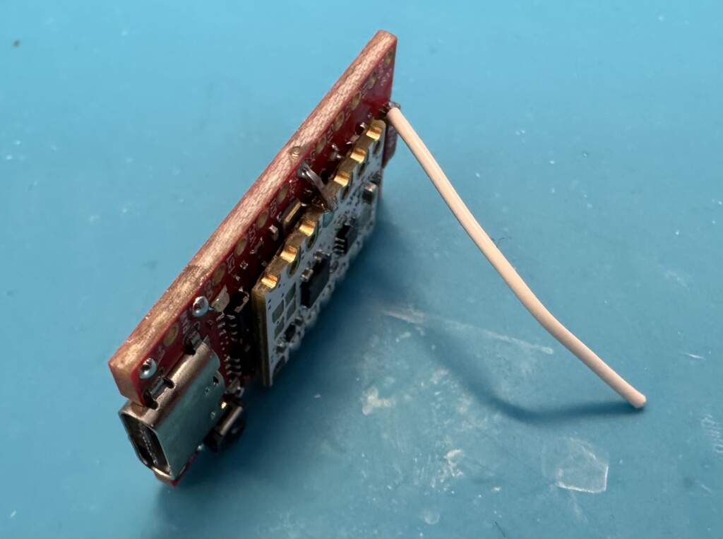
Connecting The battery
A little trick I use, is I use the Antenna Mod to hold the SuperMini upright, so I can solder the battery Negative terminal from the back side and push it in.
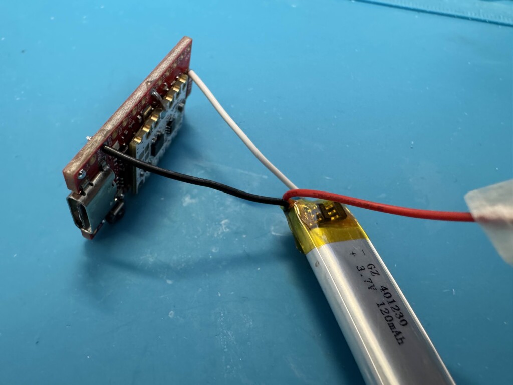
Once you have soldered the negative terminal, you can then do the final step and connect the positive terminal to B+.
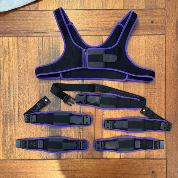
You just built a tracker <3
Put it in a case, and enjoy!
Coming soon: Pairing your trackers, calibrating, and building the Receiver.